
Civil engineering structures are designed to sustain various types of loads and possible combinations of loads that could act on them during their lifetime. Accurate estimation of the magnitudes of these loads is a very important aspect of the structural analysis process. There are local and international codes, as well as research reports and documents, that aid designers in this regard. Structural loads can be broadly classified into four groups: dead loads, live loads, impact loads, and environmental loads. These loads are briefly described in the following sections.
Dead loads are structural loads of a constant magnitude over time. They include the self-weight of structural members, such as walls, plasters, ceilings, floors, beams, columns, and roofs. Dead loads also include the loads of fixtures that are permanently attached to the structure. Prior to the analysis and design of structures, members are preliminarily sized based on architectural drawings and other relevant documents, and their weights are determined using the information available in most codes and other civil engineering literature. The recommended weight values of some commonly used materials for structural members are presented in Table 2.1. The determination of the dead load due to structural members is an iterative process. During design, member sizes and weight could change, and the process is repeated until a final member size is obtained that could support the member’s weight and the superimposed loads.
| Material | Unit Weight | |
| lb/ft 3 | kN/m 3 | |
| Reinforced concrete Plain concrete Structural steel Aluminum Brick Concrete masonry unit Wood (Douglas fir larch) Engineered wood (plywood) | 150 145 490 165 120 135 34 36 | |
| 23.60 22.60 77.00 25.90 18.90 21.20 5.30 5.7 | ||
The semi-gravity retaining wall shown in Figure 2.1 Figure 2.1 is made of mass concrete with a unit weight of 23.6 kN/m 3 . Determine the length of the wall’s weight per foot. 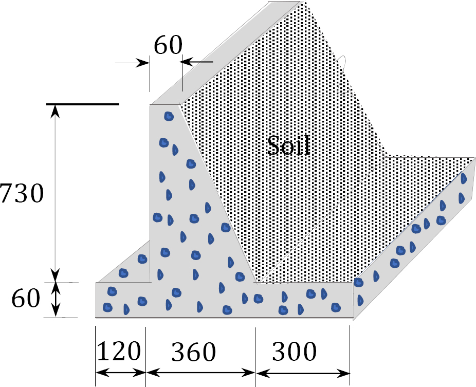 Solution Area of wall = (7.8 m)(0.6 m) + (7.3 m)(0.6 m) + (
 )(3 m)(7.3 m) = 20.01 m 2 Length of the wall’s weight per foot = 20.01 m 2 × (23.6 kN/m 3 ) = 472.24 kN/m
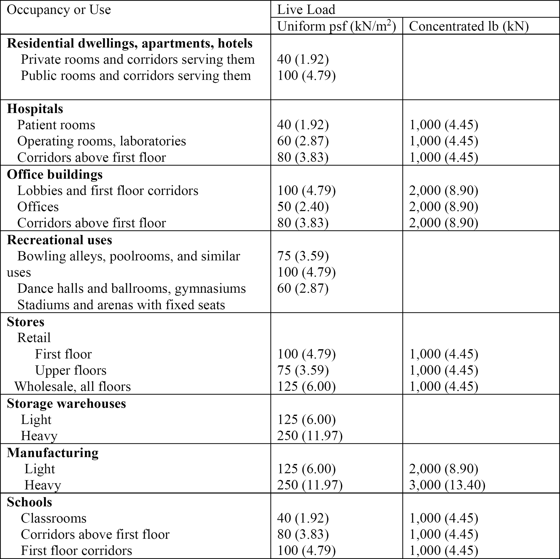
Live loads are moveable or temporarily attached to a structure. They include the loads on a building created by the storage of furniture and equipment, occupancy (people), and impact. Typical live load values are presented in Table 2.2. The loads were obtained from Table 4.3-1 in ASCE 7-16. Table 2.2. Minimum uniform and concentrated floor live loads.
The floor system of the classroom shown in Figure 2.2 consists of a 3-inch-thick reinforced concrete slab supported by steel beams. If the weight of each steel beam is 62 lb/ft, determine the dead load in lb/ft supported by any interior beam. 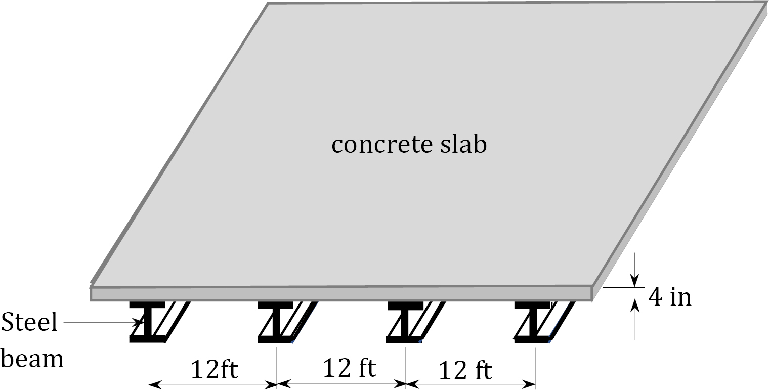 Solution Dead load due to slab weight =
  Dead load due to beam weight = 62 lb/ft Live load due to occupancy or use (classroom) = (40 lb/ft 2 )(12 ft) = 480 lb/ft Total uniform load on steel beam = 1142 lb/ft = 1.142 k/ft
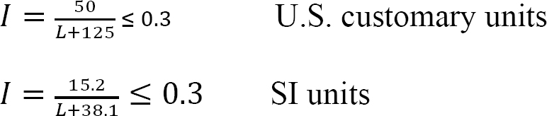
Impact loads are sudden or rapid loads applied on a structure over a relatively short period of time compared with other structural loads. They cause larger stresses in structural members than those produced by gradually applied loads of the same magnitude. Examples of impact loads are loads from moving vehicles, vibrating machinery, or dropped weights. In practice, impact loads are considered equal to imposed loads that are incremented by some percentage, called the impact factor. Some building load impact factors are presented in Table 2.3. The American Association of State Highway and Transportation Officials (AASHTO) specifies the following expression for the computation of the impact factor for a moving truck load for use in highway bridge design: where
Elevator supports and machinery
Light machinery supports
Reciprocating machine supports
Hangers supporting floors and balconies
Crane support girders and their connections